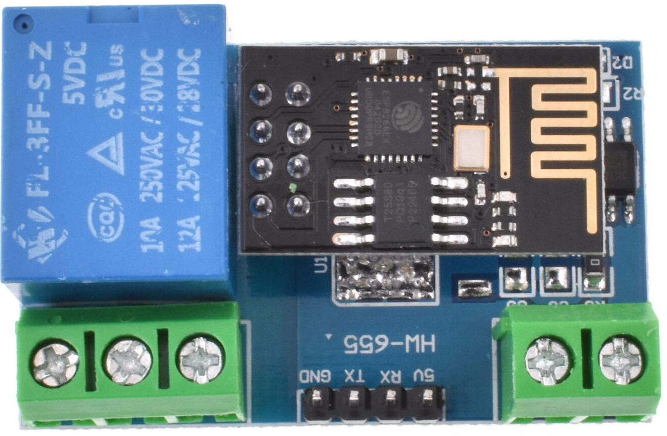
 ESP8266 RELAY LC Technology
mit ESPHome
Configuration File
esphome:

  name: esp8266-relay-lc-tech

  friendly_name: ESP8266 RELAY LC Tech esp8266:

  board: esp01_1m
# Enable Home Assistant API

api:

  ...

# Disable uart/serial logging

logger:

  baud_rate: 0
uart:

  tx_pin: 1

  rx_pin: 3

  baud_rate: 9600
switch:

  - platform: template

    name: "Relais 1"

    optimistic: true

    turn_on_action:

      - uart.write: [0xA0, 0x01, 0x01, 0xA2]

    turn_off_action:

      - uart.write: [0xA0, 0x01, 0x00, 0xA1]
ESP8266 RELAY LC Technology
mit Tasmota
Links:
- Quelle der Konsolenbefehle zum ESP8266 RELAY LC Technology: https://tasmota.github.io/docs/devices/LC-Technology-WiFi-Relay/
ESP-01 flashen
Mit tasmonizer und den ESP-Flasher (DIP-Schalter auf PROG) ein Backup erstellen und das Tasmota Image (releases) flashen. In diesem Fall ist der Speicher 1MB und die tasmota.bin sollte darauf passen. Die WiFi und die MQTT-Settings ebenfalls mit tasmonizer hochladen.
ESP-01 aus dem ESP-Flasher entfernen und auf das Board zurück stecken.
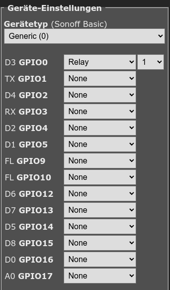
Konfiguration Tasmota
- Die IP-Adresse vom Tasmota herausfinden und auf das WebUI zugreifen
- Das alte Board verwendet 9600 Baud
- Konfiguration Modul wie im Screenshot
- Konsole:
Rule1 on System#Boot do Backlog Baudrate 9600; SerialSend5 0 endon on Power1#State=1 do SerialSend5 A00101A2 endon on Power1#State=0 do SerialSend5 A00100A1 endon
- Reboot
 ESP-01 DollaTek 4-Chan Relais
mit Tasmota
Hinweis: siehe Artikel ESP8266 RELAY LC Technology für evtl. besseren Workaround via Tasmota Rules.
Links:
ESP-01 flashen
Mit tasmonizer und den ESP-Flasher (DIP-Schalter auf PROG) ein Backup erstellen und das Tasmota Image (releases) flashen. In diesem Fall ist der Speicher 1MB und die tasmota.bin sollte darauf passen. Die WiFi und die MQTT-Settings ebenfalls mit tasmonizer hochladen.
ESP-01 aus dem ESP-Flasher entfernen und auf das Board zurück stecken.
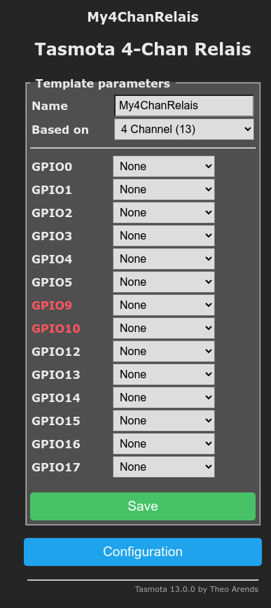
Konfiguration Tasmota
- Die IP-Adresse vom Tasmota herausfinden und auf das WebUI zugreifen, z.B. http://192.168.178.57
- Hauptmenü > Configure Module im Feld Module type 4 Channel (13) auswählen
- Hauptmenü > Configure Template einen eigenen Templatenamen vergeben und alle GPIO Pins auf None setzen
- Hauptmenü > Configure Others sollte wie folgt aussehen:
- Template:
{"NAME":"My4ChanRelais","GPIO":[0,0,0,0,0,0,0,0,0,0,0,0,0,0],"FLAG":0,"BASE":13} - Device Name: Geräteneame, erscheint so als Gerät in HomeAssistant, hier: "Tasmota 4-Chan Relais"
- Friendly Name 1: hier "Relais 1", etc
- Template:
Das Relais via Serieller Schnittstelle ansprechen
Die vier Buttons im WebUI vom Tasmota gehen nicht, da via serieller Schnittstelle ein weiterer Microcontroller auf dem Ralis-Board angesprochen werden muss und dies nicht via GPIO Ports passiert. D.h. wir verschicken Tasmota Serial Commands via MQTT um die Relais zu schalten.
In der Console vom Tasmota (via WebUI) kann man den Controller ansprechen:
SerialLog 1

Baudrate 115200

SerialSend5 A00101A2

SerialSend5 A00100A1
Für Relais 2:
SerialSend5 A00201A3

SerialSend5 A00200A2
Für Relais 3:
SerialSend5 A00301A4

SerialSend5 A00300A3
Für Relais 4:
SerialSend5 A00401A5

SerialSend5 A00400A4
Diese Befehle können auch via MQTT (MQTTfx) gesendet werden:
Publish Topic: cmnd/tasmota_4D7E7C/Backlog
Payload: Baudrate 115200; SerialSend5 A00101A2; Power1 on
- Baudrate: muss einmalig initialisiert werden
- SerialSend5: Hex-Daten an die serielle Schnittstelle
- Power1: virtualisiert, dass der Button gedrückt wurde (im WebUI)
HomeAssistant
Da der Tasmota als reiner Befehlsempfänger dient und die Steuerung über HomeAssistant erfolgt, ignorieren wir die Buttons im WebUI von Tasmota. Werden die Switches in HomeAssistant (Relais 1-4) umgeschaltet, wird das an Tasmota weitergeleitet und der (virtuelle) Status der Buttons ändert sich. D.h. Statusabfrage ist korrekt, wir müssen nur zusätzlich das physische Relais schalten:
1. Automation: Baudrate beim Start von HomeAssistant und bei Sonnenaufgang setzen
alias: Tasmota 4-Chan Relais Baudrate

description: ""

trigger:

  - platform: homeassistant

    event: start

  - platform: sun

    event: sunrise

    offset: 0

condition: []

action:

  - service: mqtt.publish

    data:

      topic: cmnd/tasmota_4D7E7C/Baudrate

      payload: "115200"

mode: single
2. Automation: Relais 1 schalten
alias: Tasmota 4-Chan Relais Relais 1 schalten

description: ""

trigger:

  - platform: device

    type: changed_states // "Umschalten"

    device_id: XXX // Geräte-ID vom Gerät "Tasmota 4-Chan Relais"

    entity_id: XXX // Entity-ID vom Schalter "Relais 1"

    domain: switch

condition: []

action:

  - if:

      - condition: device

        type: is_off

        device_id: XXX // Geräte-ID vom Gerät "Tasmota 4-Chan Relais"

        entity_id: XXX // Entity-ID vom Schalter "Relais 1"

        domain: switch

    then:

      - service: mqtt.publish

        data:

          topic: cmnd/tasmota_4D7E7C/SerialSend5

          payload: A00100A1

    else:

      - service: mqtt.publish

        data:

          payload: A00101A2

          topic: cmnd/tasmota_4D7E7C/SerialSend5

mode: single
3. bis 5. Automation, Kopie der 2. Automation erstellen und Relais und Payload austauschen (unterer Wert zuerst).
Finito.
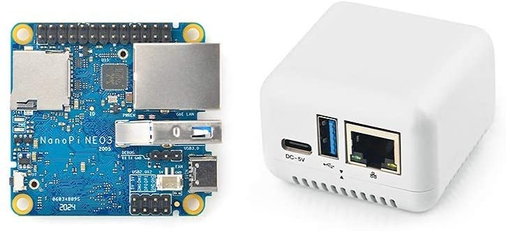 FriendlyElec Nanopi NEO3
Links:
Voraussetzungen:
FriendlyWRT oder FriendlyCore Image auf MicroSD (veraltet)- OS Download Links: https://wiki.friendlyelec.com/wiki/index.php/NanoPi_NEO3#Install_OS
- 5V 2A Netzteil USB Typ C
Nutzung/Ideen:
- Plex Media Server (via Docker) - ungetestet
- rtl_tcp - Server für Funkanwendungen
- GPIO-Ports
- NAS via USB3
- Netzwerkserver/-brücke für Glasfaser-WAN (DualStack mit CGNATv4)
- VPN-Client zu Hetzner-Server
- Port-Weiterleitung auf Hetzner-Server (VPN-Port zu Public-Port)
- Local IP:Port <-> VPN <-> Public IP:Port
FriendlyCore Ubuntu Issues:
- keine DNS Auflösung
sudo mv /etc/resolv.conf /etc/resolv.conf.oldsudo nano /etc/resolv.confnameserver 1.1.1.1
nameserver 8.8.8.8
search fritz.box
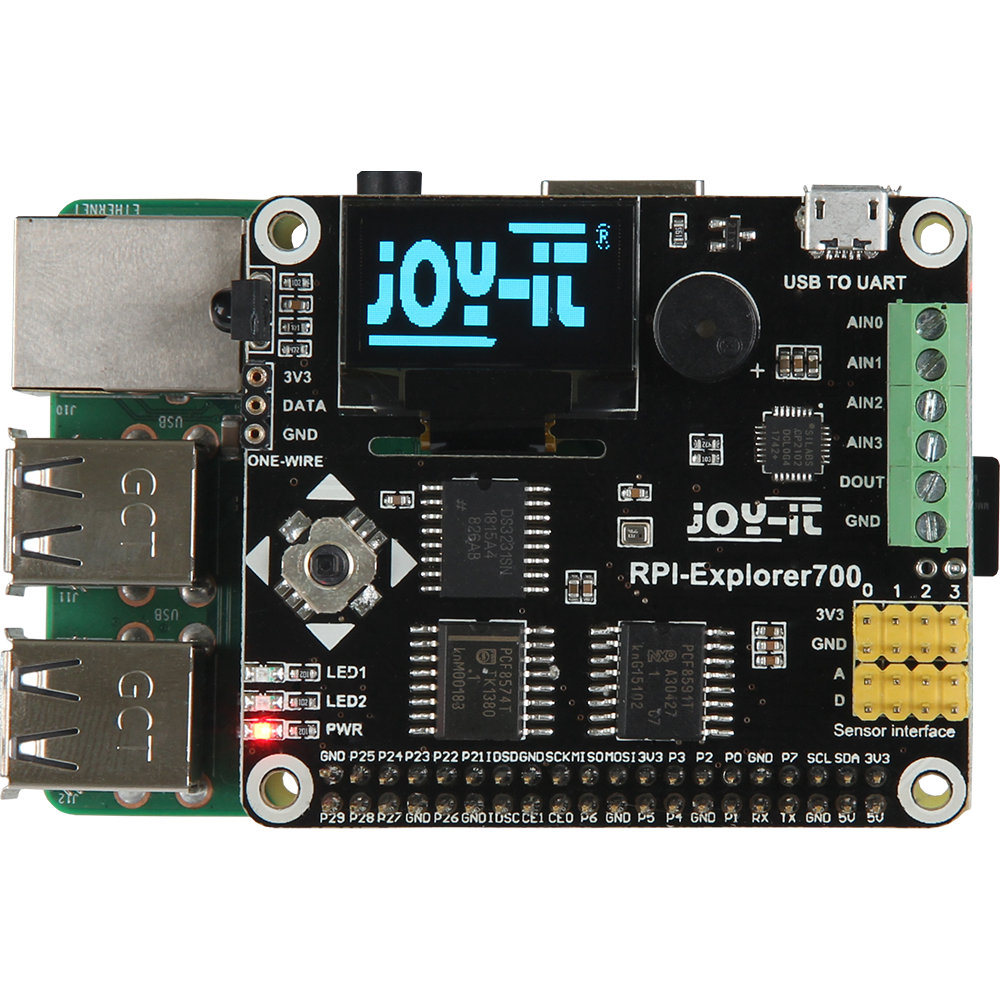 EXP700
ab Raspberry Pi 2
Code für den Raspberry Pi unter github.com/ckarrie/ckw-hass-rb-exp700.
Preis: ~20,00€
Dokumentationen vom Hersteller: joy-it.net
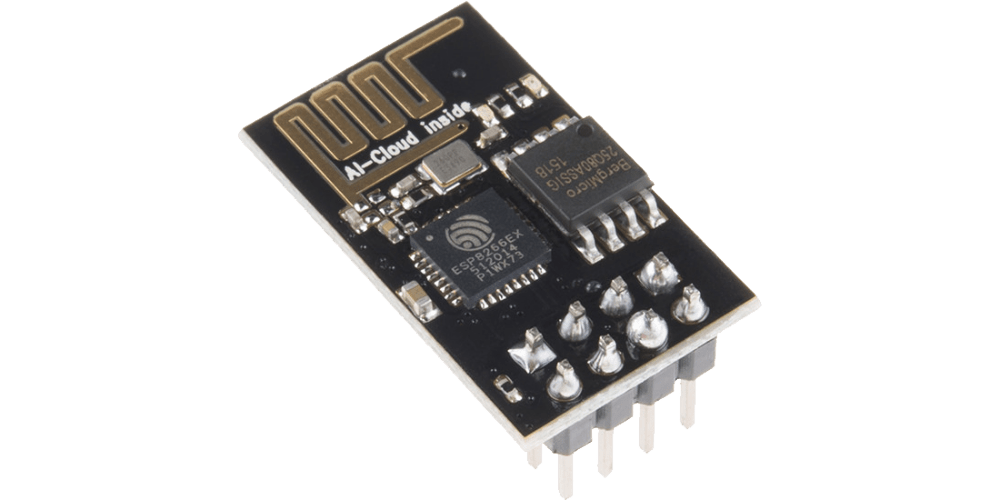 ESP8266
aka ESP-01
Links:
- WLAN-Relais (generell)
- 5V WLAN Relais
Arduino-IDE:
Unter Datei > Voreinstellungen folgende Borverwalter-URL ergänzen:
http://arduino.esp8266.com/stable/package_esp8266com_index.json
Bestand:
Aktuell besitze ich zwei ESP-01'er, auf dem einen läuft ein Webserver mit einer Dummy-Grafik, der zweite ist auf ein 5V Relais-Modul bestückt.
- Code für Webserver mit einer Dummy-Grafik: Adruino-IDE > Examples > AdvancedWebServer
- Code für Webserver für 5V Relais-Modul: WebSchalter3.1
WebSchalter3.1:
!Aktuell funktioniert das Schalten des Relais nicht, evtl. sind die Pinnummern falsch
 Netgear GS108E
Netgear Switch Integration in Homeassistant
Code für HomeAssistant unter github.com/ckarrie/ckw-ha-gs108e.
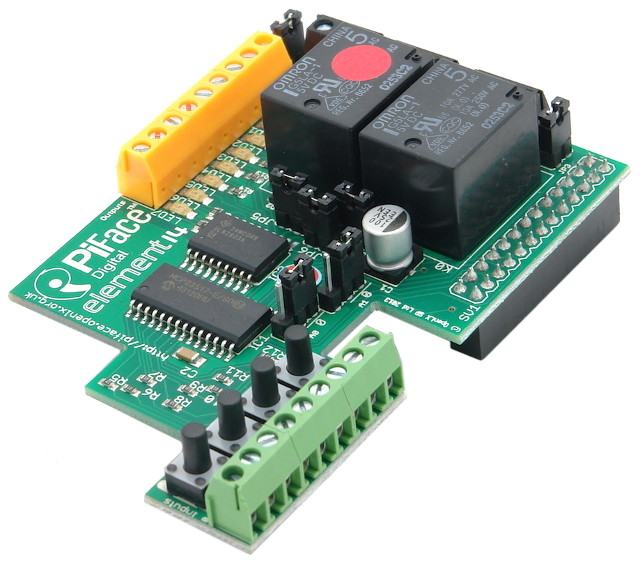 PiFace Digital
Raspberry Pi 1 mit PiFace Digital IO, MQTT und Python 3
Wir nutzen unseren alten Raspberry Pi 1 mit dem PiFace Digital und verbinden die Input- und Outputports via MQTT. Sofern Homeassistant mit eurem MQTT-Broker verbunden ist, wird das neue Gerät dank MQTT-Discovery erkannt.
Der Quellcode für den Raspberry Pi liegt unter github.com/ckarrie/ckw-ha-mqtt.
mkdir ~/src/

cd ~/src/

git clone https://github.com/ckarrie/ckw-ha-mqtt
Für Python 3 muss mit
git checkout py3
der Branch gewechselt werden.
Hardware:
- Raspberry Pi 1
- PiFace Digital (v1)
- 5V Netzteil
- SD-Karte
Software:
- Raspberry Pi OS Lite (basierend auf Debian Buster) auf SD-Karte
- MQTT-Broker
Installation:
sudo apt install python3-pip

sudo apt install screen

sudo pip3 install pifacecommon

sudo pip3 install pifacedigitalio

sudo pip3 install paho-mqtt
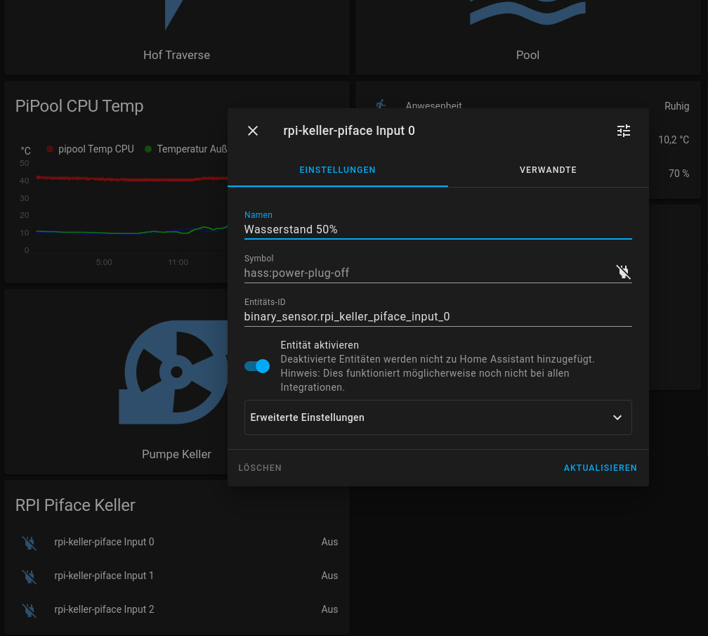
Integration in Homeassistant:
hostname ist mit dem Hostnamen von eurem Raspberry zu ersetzen.
Input Entitäts-IDs:
binary_sensor.hostname_input_0 (Eingang 0)binary_sensor.hostname_input_1 (Eingang 1)binary_sensor.hostname_input_2 (Eingang 2)binary_sensor.hostname_input_3 (Eingang 3)binary_sensor.hostname_input_4 (Eingang 4)binary_sensor.hostname_input_5 (Eingang 5)binary_sensor.hostname_input_6 (Eingang 6)binary_sensor.hostname_input_7 (Eingang 7)
Output Entitäts-IDs:
switch.hostname_switch_0 (Relais 0)switch.hostname_switch_1 (Relais 1)switch.hostname_switch_2 (Output 2)switch.hostname_switch_3 (Output 3)- usw.
Screenshots aus Homeassistant:
Auszug aus der Frontend yaml-Datei:
type: entities

entities:

  - entity: binary_sensor.rpi_keller_piface_input_0

  - entity: binary_sensor.rpi_keller_piface_input_1

  - entity: binary_sensor.rpi_keller_piface_input_2

  - entity: switch.rpi_keller_piface_switch_0

  - entity: switch.rpi_keller_piface_switch_1

title: RPI Piface Keller
 Tasmota to ESPHome
Converting Tasmota Templates to ESPHome
We use our NOUS L13T running Tasmota and migrate it to Homeassistant's ESPHome (Link to Amazon, Official Link).
After some research about GPIO formats in the Tasmota Template, I decided to migrate my NOUS L13T to ESPHome. Let's take a look at it.
GPIO Template to PIN mapping:
| GPIO | 00 | 01 | 02 | 03 | 04 | 05 | 09 | 10 | 12 | 13 | 14 | 15 | 16 | 17 |
| Name | D3 | D3 | FL | FL | D7 | D8 | D0 | A0 | ||||||
| Index of Array | 0 | 1 | 2 | 3 | 4 | 5 | 6 | 7 | 8 | 9 | 10 | 11 | 12 | 13 |
i.e. the Tasmota Template: {"NAME":"NOUS Smart breaker L13T", "GPIO": [1,161,1,160,225,224,1,1,544,1,32,1,1,1], "FLAG": 0, "BASE": 18} results in following mapping.
We use https://tasmota.github.io/docs/Components/#tasmota to look up the corresponding component. An Array Value of "1" stands for "User" an can be customized in the Tasmota WebUI.
| Array Index | Array Value | Tasmota Component | Description |
| 0 | 1 | User | |
| 1 | 161 | Switch2 | Switch, internal pull-up resistor |
| 2 | 1 | User | |
| 3 | 160 | Switch1 | Switch, internal pull-up resistor |
| 4 | 225 | Relay2 | Relay |
| 5 | 224 | Relay1 | Relay |
| 6 | 1 | User | |
| 7 | 1 | User | |
| 8 | 544 | LedLink | Link LED |
| 9 | 1 | User | |
| 10 | 32 | Button1 | Button active low, internal pull-up resistor |
| 11 | 1 | User | |
| 12 | 1 | User | |
| 13 | 1 | User |
My corresponding ESPHome yaml looks like this:
substitutions:
  devicename: "NOUS L13T Sommerküche Licht"

esphome:
  name: nous-l13t-sommerkueche-licht
  friendly_name: "${devicename}"

esp8266:
  board: esp01_1m

# Enable logging
logger:

# Enable Home Assistant API
api:
  encryption:
    key: "xxxxxxxxxxxx"

ota:
  password: "xxxxxxxxxxxx"

wifi:
  ssid: !secret wifi_ssid
  password: !secret wifi_password

  # Enable fallback hotspot
  # (captive portal) in case wifi connection fails
  ap:
    ssid: "Nous-L13T-Sommerkueche-Licht"
    password: "xxxxxxxxxxxx"

captive_portal:


# Status LED
light:
  - platform: status_led
    id: led
    pin:
      number: GPIO12
      inverted: true


binary_sensor:
  - platform: status
    name: "Status"

  # toggle relay on/off
  - platform: gpio
    name: "Button Switch 1"
    pin:
      number: GPIO03
      inverted: true
      mode:
        input: true
        pullup: true
    id: "button_state_switch_1"
    on_press:
      then:
        - switch.turn_on: "button_switch_1"
    on_release:
      then:
        - switch.turn_off: "button_switch_1"
        - switch.turn_off: "button_switch_2"

    on_double_click:
      min_length: 50ms
      max_length: 350ms
      then:
        - switch.toggle: "button_switch_2"

  - platform: gpio
    name: "Button Switch 2"
    pin:
      number: GPIO01
      inverted: true
      mode:
        input: true
        pullup: true
    id: "button_state_switch_2"
    on_press:
      - switch.toggle: "button_switch_2"


switch:
  - platform: template
    name: "Switch 1"
    icon: mdi:power
    optimistic: true
    id: "button_switch_1"
    lambda: |-
      if (id(relay_1).state) {
        return true;
      } else {
        return false;
      }
    turn_on_action:
      - switch.turn_on: relay_1
      - light.turn_on: led
    turn_off_action:
      - switch.turn_off: relay_1
      - light.turn_off: led

  - platform: template
    name: "Switch 2"
    icon: mdi:power
    optimistic: true
    id: "button_switch_2"
    lambda: |-
      if (id(relay_2).state) {
        return true;
      } else {
        return false;
      }
    turn_on_action:
      - switch.turn_on: relay_2
    turn_off_action:
      - switch.turn_off: relay_2

  - platform: gpio
    pin: GPIO05
    id: "relay_1"

  - platform: gpio
    pin: GPIO04
    id: "relay_2"
I did some "special" actions on Button Switch 1: pressing On+Off+On fast turns on Light 2 (and Light 1 is turn on by on_press).
Have fun!